Asphalt Mixing Plant – Construction Equipment

Plants

Asphalt Mixing Plant – Construction Equipment

Nowadays every country wants to enhance their economical strength more strong and powerful that is why almost each country is mainly focusing on construction of strong infrastructure of entire nation. It is true fact that strong and attractive powerful infrastructure can easily review the economical development of any country. Here strong infrastructure is referring to construction of good quality roads, and larger buildings.

There are too many objects units together to form good and strong quality roads. Among all objects, it is construction machineries like Asphalt Mixing Plant which plays significant and vital role in providing the strong forms of roads. Asphalt Mixing Plant is equipment in which various raw materials like sand, asphalt, filler, macadam, and dust particles are aggregates and combined together under accurate temperature to form strong and quality form.

Realizing about great importance and value of Asphalt mixing plant in construction of strong infrastructure different manufacturing companies has make their best effort to facilitate the market with various categories of it products. Today you can get different categories of it. Some of the names of categories are described below: -

Asphalt Drum Mix Plant

Asphalt Batch Mix Plant

Mobile Hot Mix Plant

Soil Stabilisation (Wet Mix) Plant

Mobile Concrete Plant

But before going for any categories you must closely notice about the parts and features which are implemented in Asphalt mixing Plant. You must also notice whether brand mark like ISI Certification marks are implemented on different parts of asphalt mixing plant are present or not. Only satisfying with its features you can make purchase for getting maximum satisfaction.


Thank you for visiting All About Refinery

7 Ways Profit From Asphalt and Highway Construction

By Guest Author: Robert Williams, PhD, P.E.

There is a dominant stock investing theme that directs you to invest in companies that provide a product that everybody uses every day. May I draw your attention to a specific product in this category, namely asphalt? Unless your house has a tile roof, you probably woke up under an asphalt-tiled roof; walked to your car on an asphalt footpath; drove your car to work on an asphalt-surface highway or freeway; and parked your car in the asphalt-surface office car park.

In addition, President Obama is going to re-surface all of the US deteriorating freeways and highways – using asphalt of course.

You may wish to consider investing in some of the asphalt companies identified in this article. However, most asphalt involved companies are large conglomerates and certainly the asphalt producers are the major oil and gas conglomerates some of which are listed below.

If you have not even thought of where the asphalt comes from you should be aware that it is derived from crude oil refining which primarily produces your gasoline and diesel which you also use every day.

In order to be ready for road surfacing asphalt needs to be transported from the refineries to road construction companies that combine it with various rock aggregates to provide the hard surface that you drive on. This thick black substance is only liquid at temperatures above 300 degrees Fahrenheit and requires specially designed and dedicated trucks to transport the asphalt while maintaining its temperature. I have been involved with various refinery automation projects including asphalt truck loading racks where asphalt is sold by refinery truck weigh scales (weight out minus weight in) with computer controlled and data processing for product loading authorization and custody transfer accounting/ billing for each load.

If we have international readers you should be aware that we are talking about bitumen, but not tarmac or coal tar. Tar is derived from coal and was the original road surfacing material when it was available from coal gas processing which has long been replaced by natural gas. These coal tar roads date back to the early 1800’s when John McAdam started the road surfacing referred to as tarmac or macadam roads.

Apart from the major oil companies shown in group stock charts as asphalt producers there are a large number of privately- and publicly-owned companies involved in getting the asphalt onto the roads, or car parks, or roofs. Some of these non-private companies are listed here with a brief description and their earnings estimates. According to your personalized investing criteria listed in your Trading Plan you should evaluate and exercise your due diligence as to potential investment opportunities. This is who, what, where, why and how but not the when. At this time the author has no investments in any of these companies.

Alon USA Energy, Inc. (ALJ) operates as an independent refiner and marketer of petroleum products primarily in the south central, southwestern, and western regions of the United States. ALJ has three segments: Refining and Marketing, Asphalt, and Retail. The Asphalt segment markets paving and roofing grades of asphalt, and performance-graded asphalts, emulsions, and cutbacks through its 12 refinery/terminal locations. Alon USA Energy, Inc. is a subsidiary of Alon Israel Oil Company,

asphalt_alj

Astec Industries, Inc. (ASTE) designs, engineers, manufactures and markets equipment and components used primarily in road building, utility and related construction activities. ASTE products are used in each phase of road building, from quarrying and crushing the aggregate to application of the road surface. The business segments are Asphalt Group, Aggregate and Mining Group, Mobile Asphalt Paving Group and Underground Group.

asphalt_aste

CRH plc (CRH) is an international building materials company, which manufactures and distributes building material products. The Company is organized into four divisions, two in Europe: Materials and Products & Distribution; and two in the Americas: Materials in the United States and Products & Distribution in the United States, Mexico, Canada, Chile and Argentina. Materials businesses are involved in the production of cement, aggregates, asphalt and ready-mixed concrete.

asphalt_crh

Holly Corporation (HOC) is an independent petroleum refiner, which produces light products, such as gasoline, diesel fuel and jet fuel. It owns and operates two refineries consisting of a petroleum refinery that is operated in conjunction with crude oil distillation and vacuum distillation and other facilities in New Mexico, and a refinery in Utah; owns approximately 900 miles of crude oil pipelines located principally in west Texas and New Mexico; owns and operates Holly Asphalt Company, along with other assets including approximately 1,700 miles of petroleum product pipelines located in Texas, New Mexico and Oklahoma; 10 refined product terminals; and two refinery truck rack facilities.

asphalt_hoc

NuStar Energy L.P. (NS) provides storage and truck loading terminal services for crude oil and refined petroleum products to the producers of crude oil, integrated oil companies, chemical companies, oil traders and refiners. NS has five business segments: refined product terminals, refined product pipelines, crude oil pipelines, crude oil storage tanks and marketing. In March 2008, NS announced that it has completed its acquisition of CITGO Asphalt Refining Company’s asphalt operations and assets which is the primary reason for including them in this Asphalt article.

asphalt_ns

Terex Corporation (TEX) is a diversified global manufacturer of capital equipment for the construction, infrastructure, quarrying, surface mining, shipping, transportation, refining and utility industries.

asphalt_tex

Vulcan Materials Company (VMC) is a producer of construction aggregates, primarily crushed stone, sand and gravel, a producer of asphalt and concrete and a producer of cement in Florida. The Company operates through three segments: Aggregates, Asphalt mix and Concrete, and Cement.

asphalt_vmc

asphalt_oils

asphalt_construction

If you are familiar with other listed asphalt handling companies the author and the readers would appreciate knowing about them via the comments input section below

Author Bio:

Robert Williams 40 plus years experience includes oil/gas engineering in crude oil/petroleum products/natural gas, refining, processing and pipelines on all continents, except South America and Antarctica, from Alaska and Australia pipelines to S.E. Asia offshore, from UK North Sea to Los Angeles fuel truck racks and from Romanian pipelines to West Africa FPSO.


Thank you for visiting All About Refinery

Distillation Oil Refining

Crude oil, also called petroleum, is a complex mixture of carbon and hydrogen (hydrocarbons), which exist as a liquid in the earth's crust. Crude oil has many compositions, some is black, thick and tar like, while other crude oils are lighter in color and thinner. The carbon and hydrogen in crude oil are thought to have originated from the remains of microscopic marine organisms that were deposited at the bottom of seas and oceans and was transformed at high temperature and pressure into crude oil and natural gas.


This oil and gas migrates upward through the porous rock, as it is less dense than the water which fills the pores. The oil and gas is trapped by a layer of impermeable rock through which they can't flow. Several different types of oil and gas "traps" exist; a common dome formed by folded sedimentary rocks. Crude oil is obtained by drilling a hole into the reservoir rock (sandstone, limestone etc.) and pumping it out.

Petroleum refining is the process of separating the many compounds present in crude petroleum. This process is called fractional distillation where the crude oil is heated; the various of the compounds boil at different temperatures and change to gases; and are later recondensed back into liquids. Fossil Fuels

The principle which is used is that the longer the carbon chain, the higher the temperature at which the compounds will boil.
Boiling Points and Hydrocarbons

The crude petroleum is heated and changed into a gas. The gases are passed through a distillation column which becomes cooler as the height increases. See the figure on the left. When a compound in the gaseous state cools below its boiling point, it condenses into a liquid. The liquids may be drawn off the distilling column at various heights.
Although all fractions of petroleum find uses, the greatest demand is for gasoline. One barrel of crude petroleum contains only 25-35% gasoline. Transportation demands require that over 50% of the crude oil be converted into gasoline. To meet this demand some petroleum fractions must be converted to gasoline. This may be done by "cracking" - breaking down large molecules of heavy heating oil; "reforming" - changing molecular structures of low quality gasoline molecules; or "polymerization" - forming longer molecules from smaller ones. Conversion Oil Refining
For example if decane is heated to about 500 C the covalent carbon-carbon bonds begin to break during the cracking process. Many kinds of compounds including alkenes are made during the cracking process. Alkenes are formed because there are not enough hydrogens to saturate all bonding positions after the carbon-carbon bonds are broken.

Thank you for visiting All About Refinery

Cupellation

Cupellation is a process used to separate noble metals such as gold or silver from base metals such as lead. It is often used to assay gold in order to test its purity. Sometimes cupellation is called "fire assaying." It was formerly the usual process for extracting silver from lead.

In this process, an alloy consisting of both noble and base metals is placed in a crucible. This mixture is then melted and allowed to freeze. When solidified, a button consisting of precious metals and lead can be removed from the slag of metal oxides and other materials. When assaying ores this slag layer can be quite massive, but when assaying karat gold, it is virtually non-existent. After cooling, the metals are placed in a special pot made of bone ash or clay called a cupel. Under high heat, lead turns to litharge, a lead oxide, which is absorbed by the cupel or lost to the atmosphere. At the end of the cupellation process, a button of pure gold and silver remains in the bottom of the cupel. The button is then placed in nitric acid to dissolve the silver, and the remaining pure (24k) gold weighed to determine the gold content present in the original starting material.

http://www.carbolite.com/imagelib%5CCF24.jpg

Loss of lead to the larger atmosphere creates an environmental hazard, and so this larger loss should be restrained by appropriate equipment and lead recovery means.

http://www.preciousmetals.umicore.com/process/PMO/smelter_Matte_tapping_via_fENb.jpg

Historically, cupellation was not merely a method of assaying, but also the main means of extracting silver from lead. It produced litharge in large quantities which was usually resmelted to lead.

Thank you for visiting All About Refinery

Petroleum

Petroleum (L. petroleum, from Greek πετρέλαιον, lit. "rock oil") or crude oil is a naturally occurring, flammable liquid found in rock formations in the Earth consisting of a complex mixture of hydrocarbons of various molecular weights, plus other organic compounds.

The term "petroleum" was first used in the treatise De Natura Fossilium, published in 1546 by the German mineralogist Georg Bauer, also known as Georgius Agricola.

http://www.morganyoungconsultants.com/assets/images/petroleum.jpg

http://www.stockwatch.in/files/petroleum.jpg

Composition

The proportion of hydrocarbons in the mixture is highly variable and ranges from as much as 97% by weight in the lighter oils to as little as 50% in the heavier oils and bitumens.

The hydrocarbons in crude oil are mostly alkanes, cycloalkanes and various aromatic hydrocarbons while the other organic compounds contain nitrogen, oxygen and sulfur, and trace amounts of metals such as iron, nickel, copper and vanadium. The exact molecular composition varies widely from formation to formation but the proportion of chemical elements vary over fairly narrow limits as follows:

omposition by weight
Element Percent range
Carbon 83 to 87%
Hydrogen 10 to 14%
Nitrogen 0.1 to 2%
Oxygen 0.1 to 1.5%
Sulfur 0.5 to 6%
Metals less than 1000 ppm
Four different types of hydrocarbon molecules appear in crude oil. The relative percentage of each varies from oil to oil, determining the properties of each oil.

The Refining Process

What Is A Refinery?

A refinery is a factory. Just as a paper mill turns lumber into paper, a refinery takes crude oil and turns it into gasoline and hundreds of other useful products. A typical refinery costs billions of dollars to build and millions more to maintain. A refinery runs twenty-four hours a day, 365 days a year and requires a large number of employees to run. A refinery can occupy as much land as several hundred football fields. Workers ride bicycles to move from place to place inside the complex.

Today, some refineries turn more than half of every 42-gallon barrel of crude oil into gasoline. How does this transformation take place? Essentially, refining breaks crude oil down into its various components, which then are selectively reconfigured into new products. All refineries perform three basic steps: separation, conversion, and treatment.

Separation

Heavy petroleum fractions are on the bottom, light fractions are on the top. This allows the separation of the various petrochemicals. Modern separation involves piping oil through hot furnaces. The resulting liquids and vapors are discharged into distillation towers. Inside the towers, the liquids and vapors separate into components or fractions according to weight and boiling point. The lightest fractions, including gasoline and liquid petroleum gas (LPG), vaporize and rise to the top of the tower, where they condense back to liquids. Medium weight liquids, including kerosene and diesel oil distillates, stay in the middle. (Heavier liquids, called gas oils, separate lower down, while the heaviest fractions with the highest boiling points settle at the bottom.)

Conversion

Cracking and rearranging molecules adds value to the products. This is where refining’s fanciest footwork takes place–where fractions from the distillation towers are transformed into streams (intermediate components) that eventually become finished products. The most widely used conversion method is called cracking because it uses heat and pressure to “crack” heavy hydrocarbon molecules into lighter ones. A cracking unit consists of one or more tall, thick-walled, bullet-shaped reactors and a network of furnaces, heat exchangers and other vessels.Cracking and coking are not the only forms of conversion. Other refinery processes, instead of splitting molecules, rearrange them to add value. Alkylation’s, for example, makes gasoline components by combining some of the gaseous byproducts of cracking. The process, which essentially is cracking in reverse, takes place in a series of large, horizontal vessels and tall, skinny towers that loom above other refinery structures. Reforming uses heat, moderate pressure and catalysts to turn naphtha, a light, relatively low-value fraction, into high-octane gasoline components.

Treatment

The finishing touches occur during the final treatment. To make gasoline, refinery technicians carefully combine a variety of streams from the processing units. Among the variables that determine the blend are octane level, vapor pressure ratings and special considerations, such as whether the gasoline will be used at high altitudes.

Storage

Both the incoming crude oil and the outgoing final products need to be stored. These liquids are stored in large tanks on a tank farm. Pipelines carry the final products from the tank farm near the refinery to other tanks all across the country.

Source: Energy Information Administration

Treating and Blending the Fractions

Distillated and chemically processed fractions are treated to remove impurities, such as organic compounds containing sulfur, nitrogen, oxygen, water, dissolved metals and inorganic salts. Treating is usually done by passing the fractions through the following:
  • a column of sulfuric acid - removes unsaturated hydrocarbons (those with carbon-carbon double-bonds), nitrogen compounds, oxygen compounds and residual solids (tars, asphalt)
  • an absorption column filled with drying agents to remove water
  • sulfur treatment and hydrogen-sulfide scrubbers to remove sulfur and sulfur compounds

Photo courtesy Phillips Petroleum
Plastics produced from refined oil fractions
After the fractions have been treated, they are cooled and then blended together to make various products, such as:
  • gasoline of various grades, with or without additives
  • lubricating oils of various weights and grades (e.g. 10W-40, 5W-30)
  • kerosene of various various grades
  • jet fuel
  • diesel fuel
  • heating oil
  • chemicals of various grades for making plastics and other polymers
For more information on the fascinating world of oil refining and petroleum chemistry.

Chemical Processing

You can change one fraction into another by one of three methods:
  • breaking large hydrocarbons into smaller pieces (cracking)
  • combining smaller pieces to make larger ones (unification)
  • rearranging various pieces to make desired hydrocarbons (alteration)

Cracking
Cracking takes large hydrocarbons and breaks them into smaller ones.


Cracking breaks large chains into smaller chains.

There are several types of cracking:

  • Thermal - you heat large hydrocarbons at high temperatures (sometimes high pressures as well) until they break apart.
    • steam - high temperature steam (1500 degrees Fahrenheit / 816 degrees Celsius) is used to break ethane, butane and naptha into ethylene and benzene, which are used to manufacture chemicals.
    • visbreaking - residual from the distillation tower is heated (900 degrees Fahrenheit / 482 degrees Celsius), cooled with gas oil and rapidly burned (flashed) in a distillation tower. This process reduces the viscosity of heavy weight oils and produces tar.
    • coking - residual from the distillation tower is heated to temperatures above 900 degrees Fahrenheit / 482 degrees Celsius until it cracks into heavy oil, gasoline and naphtha. When the process is done, a heavy, almost pure carbon residue is left (coke); the coke is cleaned from the cokers and sold.


    Photo courtesy Phillips Petroleum Company
    Catalysts used in catalytic cracking or reforming
  • Catalytic - uses a catalyst to speed up the cracking reaction. Catalysts include zeolite, aluminum hydrosilicate, bauxite and silica-alumina.
    • fluid catalytic cracking - a hot, fluid catalyst (1000 degrees Fahrenheit / 538 degrees Celsius) cracks heavy gas oil into diesel oils and gasoline.
    • hydrocracking - similar to fluid catalytic cracking, but uses a different catalyst, lower temperatures, higher pressure, and hydrogen gas. It takes heavy oil and cracks it into gasoline and kerosene (jet fuel).
After various hydrocarbons are cracked into smaller hydrocarbons, the products go through another fractional distillation column to separate them.

Unification

Sometimes, you need to combine smaller hydrocarbons to make larger ones -- this process is called unification. The major unification process is called catalytic reforming and uses a catalyst (platinum, platinum-rhenium mix) to combine low weight naphtha into aromatics, which are used in making chemicals and in blending gasoline. A significant by-product of this reaction is hydrogen gas, which is then either used for hydrocracking or sold.


A reformer combines chains.
Alteration
Sometimes, the structures of molecules in one fraction are rearranged to produce another. Commonly, this is done using a process called alkylation. In alkylation, low molecular weight compounds, such as propylene and butylene, are mixed in the presence of a catalyst such as hydrofluoric acid or sulfuric acid (a by-product from removing impurities from many oil products). The products of alkylation are high octane hydrocarbons, which are used in gasoline blends to reduce knocking (see "What does octane mean?" for details).


Rearranging chains.

Now that we have seen how various fractions are changed, we will discuss the how the fractions are treated and blended to make commercial products.


An oil refinery is a combination of all of these units.

Fractional Distillation


Photo courtesy Phillips Petroleum
Distillation columns in an oil refinery
The various components of crude oil have different sizes, weights and boiling temperatures; so, the first step is to separate these components. Because they have different boiling temperatures, they can be separated easily by a process called fractional distillation. The steps of fractional distillation are as follows:
  1. You heat the mixture of two or more substances (liquids) with different boiling points to a high temperature. Heating is usually done with high pressure steam to temperatures of about 1112 degrees Fahrenheit / 600 degrees Celsius.
  2. The mixture boils, forming vapor (gases); most substances go into the vapor phase.
  3. The vapor enters the bottom of a long column (fractional distillation column) that is filled with trays or plates.
    • The trays have many holes or bubble caps (like a loosened cap on a soda bottle) in them to allow the vapor to pass through.
    • The trays increase the contact time between the vapor and the liquids in the column.
    • The trays help to collect liquids that form at various heights in the column.
    • There is a temperature difference across the column (hot at the bottom, cool at the top).
  4. The vapor rises in the column.
  5. As the vapor rises through the trays in the column, it cools.
  6. When a substance in the vapor reaches a height where the temperature of the column is equal to that substance's boiling point, it will condense to form a liquid. (The substance with the lowest boiling point will condense at the highest point in the column; substances with higher boiling points will condense lower in the column.).
  7. The trays collect the various liquid fractions.
  8. The collected liquid fractions may:
    • pass to condensers, which cool them further, and then go to storage tanks
    • go to other areas for further chemical processing
Fractional distillation is useful for separating a mixture of substances with narrow differences in boiling points, and is the most important step in the refining process.

The oil refining process starts with a fractional distillation column. On the right, you can see several chemical processors that are described in the next section.

Very few of the components come out of the fractional distillation column ready for market. Many of them must be chemically processed to make other fractions. For example, only 40% of distilled crude oil is gasoline; however, gasoline is one of the major products made by oil companies. Rather than continually distilling large quantities of crude oil, oil companies chemically process some other fractions from the distillation column to make gasoline; this processing increases the yield of gasoline from each barrel of crude oil.

In the next section, we'll look at how we chemically process one fraction into another.

How Oil Refining Works

The Refining Process

As mentioned previously, a barrel of crude oil has a mixture of all sorts of hydrocarbons in it. Oil refining separates everything into useful substances. Chemists use the following steps:
  1. The oldest and most common way to separate things into various components (called fractions), is to do it using the differences in boiling temperature. This process is called fractional distillation. You basically heat crude oil up, let it vaporize and then condense the vapor.
  2. Newer techniques use Chemical processing on some of the fractions to make others, in a process called conversion. Chemical processing, for example, can break longer chains into shorter ones. This allows a refinery to turn diesel fuel into gasoline depending on the demand for gasoline.
  3. Refineries must treat the fractions to remove impurities.
  4. Refineries combine the various fractions (processed, unprocessed) into mixtures to make desired products. For example, different mixtures of chains can create gasolines with different octane ratings.


Photo courtesy Phillips Petroleum Company
An oil refinery

The products are stored on-site until they can be delivered to various markets such as gas stations, airports and chemical plants. In addition to making the oil-based products, refineries must also treat the wastes involved in the processes to minimize air and water pollution.

In the next section, we will look at how we separate crude oil into its components.

Crystal Structure

In mineralogy and crystallography, a crystal structure is a unique arrangement of atoms in a crystal. A crystal structure is composed of a motif, a set of atoms arranged in a particular way, and a lattice. Motifs are located upon the points of a lattice, which is an array of points repeating periodically in three dimensions. The points can be thought of as forming identical tiny boxes, called unit cells, that fill the space of the lattice. The lengths of the edges of a unit cell and the angles between them are called the lattice parameters. The symmetry properties of the crystal are embodied in its space group. A crystal's structure and symmetry play a role in determining many of its properties, such as cleavage, electronic band structure, and optical properties.

http://newton.ex.ac.uk/research/qsystems/people/sque/images/diamond-conventional-unit-cell.gif

Unit cell

The crystal structure of a material or the arrangement of atoms in a crystal structure can be described in terms of its unit cell. The unit cell is a tiny box containing one or more motifs, a spatial arrangement of atoms. The unit cells stacked in three-dimensional space describe the bulk arrangement of atoms of the crystal. The crystal structure has a three dimensional shape. The unit cell is given by its lattice parameters, the length of the cell edges and the angles between them, while the positions of the atoms inside the unit cell are described by the set of atomic positions (xi,yi,zi) measured from a lattice point.

http://media-2.web.britannica.com/eb-media/14/7514-004-D4165217.gif

Although there are an infinite number of ways to specify a unit cell, for each crystal structure there is a conventional unit cell, which is chosen to display the full symmetry of the crystal (see below). However, the conventional unit cell is not always the smallest possible choice. A primitive unit cell of a particular crystal structure is the smallest possible volume one can construct with the arrangement of atoms in the crystal such that, when stacked, completely fills the space. This primitive unit cell will not always display all the symmetries inherent in the crystal. A Wigner-Seitz cell is a particular kind of primitive cell which has the same symmetry as the lattice. In a unit cell each atom has an identical environment when stacked in 3 dimensional space. In a primitive cell, each atom may not have the same environment.

Classification of crystals by symmetry

The defining property of a crystal is its inherent symmetry, by which we mean that under certain 'operations' the crystal remains unchanged. For example, rotating the crystal 180 degrees about a certain axis may result in an atomic configuration which is identical to the original configuration. The crystal is then said to have a twofold rotational symmetry about this axis. In addition to rotational symmetries like this, a crystal may have symmetries in the form of mirror planes and translational symmetries, and also the so-called compound symmetries which are a combination of translation and rotation/mirror symmetries. A full classification of a crystal is achieved when all of these inherent symmetries of the crystal are identified.

Equipment for Crystallization

1. Tank crystallizers. Tank crystallization is an old method still used in some specialized cases. Saturated solutions, in tank crystallization, are allowed to cool in open tanks. After a period of time the mother liquid is drained and the crystals removed. Nucleation and size of crystals are difficult to control. Typically, labor costs are very high.

http://www.chemicalequipmentsindia.com/images/crystlizer.jpg

2. Scraped surface crystallizers. One type of scraped surface crystallizer is the Swenson-Walker crystallizer, which consists of an open trough 0.6m wide with a semicircular bottom having a cooling jacket outside. A slow-speed spiral agitator rotates and suspends the growing crystals on turning. The blades pass close to the wall and break off any deposits of crystals on the cooled wall. The product generally has a somewhat wide crystal-size distribution.

http://jolisfukyu.tokai-sc.jaea.go.jp/fukyu/mirai-en/2008/img/honbun/1-26.jpg

3. Double-pipe scraped surface crystallizer. Also called a votator, this type of crystallizer is used in crystallizing ice cream and plasticizing margarine. Cooling water passes in the annular space. An internal agitator is fitted with spring-loaded scrapers that wipe the wall and provide good heat-transfer coefficients.

http://tender-suba.com/wp-content/uploads/2009/03/crystallizers.jpg

4. Circulating-liquid evaporator-crystallizer. Also called Oslo crystallizer. Here supersaturation is reached by evaporation. The circulating liquid is drawn by the screw pump down inside the tube side of the condensing stream heater. The heated liquid then flows into the vapor space, where flash evaporation occurs, giving some supersaturation.The vapor leaving is condensed. The supersaturated liquid flows down the downflow tube and then up through the bed of fluidized and agitated crystals, which are growing in size. The leaving saturated liquid then goes back as a recycle stream to the heater, where it is joined by the entering fluid. The larger crystals settle out and slurry of crystals and mother liquid is withdrawn as a product.

5. Circulating-magma vacuum crystallizer. The magma or suspension of crystals is circulated out of the main body through a circulating pipe by a screw pump. The magma flows though a heater, where its temperature is raised 2-6 K. The heated liquor then mixes with body slurry and boiling occurs at the liquid surface. This causes supersaturation in the swirling liquid near the surface, which deposits in the swirling suspended crystals until they leave again via the circulating pipe. The vapors leave through the top. A steam-jet ejector provides vacuum.

6. Continuous oscillatory baffled crystallizer (COBCTM). The COBCTM is a tubular baffled crystallizer that offers plug flow under laminar flow conditions (low flow rates) with superior heat transfer coefficient, allowing controlled cooling profiles, e.g. linear, parobolic, discontinued, step-wise or any type, to be achieved. This gives much better control over crystal size, morphology and consistent crystal products. For further information see oscillatory baffled reactor.

Crystallization

Crystallization is the (natural or artificial) process of formation of solid crystals precipitating from a solution, melt or more rarely deposited directly from a gas. Crystallization is also a chemical solid-liquid separation technique, in which mass transfer of a solute from the liquid solution to a pure solid crystalline phase occurs.

http://www.cheresources.com/cryst5.jpg

Process

The crystallization process consists of two major events, nucleation and crystal growth. Nucleation is the step where the solute molecules dispersed in the solvent start to gather into clusters, on the nanometer scale (elevating solute concentration in a small region), that becomes stable under the current operating conditions. These stable clusters constitute the nuclei. However when the clusters are not stable, they redissolve. Therefore, the clusters need to reach a critical size in order to become stable nuclei. Such critical size is dictated by the operating conditions (temperature, supersaturation, etc.). It is at the stage of nucleation that the atoms arrange in a defined and periodic manner that defines the crystal structure — note that "crystal structure" is a special term that refers to the relative arrangement of the atoms, not the macroscopic properties of the crystal (size and shape), although those are a result of the internal crystal structure.

The crystal growth is the subsequent growth of the nuclei that succeed in achieving the critical cluster size. Nucleation and growth continue to occur simultaneously while the supersaturation exists. Supersaturation is the driving force of the crystallization, hence the rate of nucleation and growth is driven by the existing supersaturation in the solution. Depending upon the conditions, either nucleation or growth may be predominant over the other, and as a result, crystals with different sizes and shapes are obtained (control of crystal size and shape constitutes one of the main challenges in industrial manufacturing, such as for pharmaceuticals). Once the supersaturation is exhausted, the solid-liquid system reaches equilibrium and the crystallization is complete, unless the operating conditions are modified from equilibrium so as to supersaturate the solution again.

http://upload.wikimedia.org/wikipedia/commons/c/c1/Snow_crystallization_in_Akureyri_2005-02-26_16-33-10.jpeg

Many compounds have the ability to crystallize with different crystal structures, a phenomenon called polymorphism. Each polymorph is in fact a different thermodynamic solid state and crystal polymorphs of the same compound exhibit different physical properties, such as dissolution rate, shape (angles between facets and facet growth rates), melting point, etc. For this reason, polymorphism is of major importance in industrial manufacture of crystalline products.


Crushers By Compaction Method

Jaw crusher

http://www.raymondmill.cn/stone_crusher/images/JawAni.gif

A jaw or toggle crusher consists of a set of vertical jaws, one jaw being fixed and the other being moved back and forth relative to it by a cam or pitman mechanism. The jaws are farther apart at the top than at the bottom, forming a tapered chute so that the material is crushed progressively smaller and smaller as it travels downward until it is small enough to escape from the bottom opening. The movement of the jaw can be quite small, since complete crushing is not performed in one stroke.

The inertia required to crush the material is provided by a weighted flywheel that moves a shaft creating an eccentric motion that causes the closing of the gap.


Single and double toggle jaw crushers are constructed of heavy duty fabricated plate frames with reinforcing ribs throughout. The crushers components are of high strength design to accept high power draw. Manganese steel is used for both fixed and movable jaw faces. Heavy flywheels allow crushing peaks on tough materials

Double Toggle jaw crushers may feature hydraulic toggle adjusting mechanisms.

Gyratory crusher

A gyratory crusher is similar in basic concept to a jaw crusher, consisting of a concave surface and a conical head; both surfaces are typically lined with manganese steel surfaces. The inner cone has a slight circular movement, but does not rotate; the movement is generated by an eccntric arrangement. As with the jaw crusher, material travels downward between the two surfaces being progressively crushed until it is small enough to fall out through the gap between the two surfaces.

http://www.quarrying.org/dictionary/images/g/Gyratory-crusher.gif

A Gyratory Crusher is one of the main types of primary crushers in a mine or ore processing plant. Gyratory crushers are designated in size either by the gape and mantle diameter or by the size of the receiving opening. Gyratory crushers can be used for primary or secondary crushing. The crushing action is caused by the closing of the gap between the mantle line (movable) mounted on the central vertical spindle and the concave liners (fixed) mounted on the main frame of the crusher. The gap is opened and closed by an eccentric on the bottom of the spindle that causes the central vertical spindle to gyrate. The vertical spindle is free to rotate around its own axis. The crusher illustrated is a short-shaft suspended spindle type, meaning that the main shaft is suspended at the top and that the eccentric is mounted above the gear. The short-shaft design has superseded the long-shaft design in which the eccentric is mounted below the gear

http://www.flsmidthminerals.com/NR/rdonlyres/830DC584-6D56-41C8-A336-BA08AA357F5E/32400/Gyratory.jpg

As an example, a Fuller-Traylor gyratory crusher features throughputs to 12,000 TPH with installed powers to 1,300 hp (970 kW).

http://www.impact-crushers.com/pic/Impact-Crushers.gif

Impact crushers

Impact crushers involve the use of impact rather than pressure to crush material. The material is contained within a cage, with openings on the bottom, end, or side of the desired size to allow pulverized material to escape. This type of crusher is usually used with soft and non-abrasive material such as coal, seeds, limestone, gypsum or soft metallic ores.

http://www.jaw-crushers.cn/pic/Impact-Crusher.jpg

Crusher

A crusher is a machine designed to reduce large solid material objects into a smaller volume, or smaller pieces. Crushers may be used to reduce the size, or change the form, of waste materials so they can be more easily disposed of or recycled, or to reduce the size of a solid mix of raw materials (as in rock ore), so that pieces of different composition can be differentiated. Crushing is the process of transferring a force amplified by mechanical advantage through a material made of molecules that bond together more strongly, and resist deformation more, than those in the material being crushed do. Crushing devices hold material between two parallel or tangent solid surfaces, and apply sufficient force to bring the surfaces together to generate enough energy within the material being crushed so that its molecules separate from (fracturing), or change alignment in relation to (deformation), each other. The earliest crushers were hand-held stones, where the weight of the stone provided a boost to muscle power, used against a stone anvil. Querns and mortars are types of these crushing devices.

http://static.howstuffworks.com/gif/crusher-3.jpg

In industry, a crusher is typically a machine which uses a metal surface to break or compress materials. Mining operations use crushers, commonly classified by the degree to which they fragment the starting material, with primary and secondary crushers handling coarse materials, and tertiary and quaternary crushers reducing ore particles to finer gradations. Typically, crushing stages are followed by milling stages if the materials needs to be further reduced. Crushers are used to reduce particle size enough so that the material can be processed into finer particles in a grinder. A typical circuit at a mine might consist of a crusher followed by a SAG mill followed by a ball mill. In this context, the SAG mill and ball mill are considered grinders rather than crushers.

http://www.aggregatepros.com/images/fintec%201107%20Jaw%20crusher.jpg

Furnace


A furnace is a device used for heating. The name derives from Latin fornax, oven. The earliest furnace was excavated at Balakot, a site of the Indus Valley Civilization, dating back to its mature phase (c. 2500-1900 BC). The furnace was most likely used for the manufacturing of ceramic objects.
In American English and Canadian English, the term furnace on its own is generally used to describe household heating systems based on a central furnace (known either as a boiler or a heater in British English), and sometimes as a synonym for kiln, a device used in the production of ceramics. In British English the term furnace is used exclusively to mean industrial furnaces which are used for many things, such as the extraction of metal from ore (smelting) or in oil refineries and other chemical plants, for example as the heat source for fractional distillation columns.
The term furnace can also refer to a direct fired heater, used in boiler applications in chemical industries or for providing heat to chemical reactions for processes like cracking, and is part of the standard English names for many metallurgical furnaces worldwide.
The heat energy to fuel a furnace may be supplied directly by fuel combustion, by electricity such as the electric arc furnace, or through Induction heating in induction furnaces.

Heat exchanger


A heat exchanger is a device built for efficient heat transfer from one medium to another, whether the media are separated by a solid wall so that they never mix, or the media are in direct contact. They are widely used in space heating, refrigeration, air conditioning, power plants, chemical plants, petrochemical plants, petroleum refineries, and natural gas processing. One common example of a heat exchanger is the radiator in a car, in which the heat source, being a hot engine-cooling fluid, water, transfers heat to air flowing through the radiator
Types of heat exchangers

Shell and tube heat exchanger A Shell and Tube heat exchangerMain article: Shell and tube heat exchangerShell and tube heat exchangers consist of a series of tubes. One set of these tubes contains the fluid that must be either heated or cooled. The second fluid runs over the tubes that are being heated or cooled so that it can either provide the heat or absorb the heat required. A set of tubes is called the tube bundle and can be made up of several types of tubes: plain, longitudinally finned, etc. Shell and Tube heat exchangers are typically used for high pressure applications (with pressures greater than 30 bar and temperatures greater than 260°C.[This is because the shell and tube heat exchangers are robust due to their shape.There are several thermal design features that are to be taken into account when designing the tubes in the shell and tube heat exchangers. These include:
Tube diameter: Using a small tube diameter makes the heat exchanger both economical and compact. However, it is more likely for the heat exchanger to foul up faster and the small size makes mechanical cleaning of the fouling difficult. To prevail over the fouling and cleaning problems, larger tube diameters can be used. Thus to determine the tube diameter, the available space, cost and the fouling nature of the fluids must be considered. Tube thickness: The thickness of the wall of the tubes is usually determined to ensure: There is enough room for corrosion That flow-induced vibration has resistance Axial strength Ability to easily stock spare parts costSometimes the wall thickness is determined by the maximum pressure differential across the wall.
Plate heat exchanger
Main article: Plate heat exchangerAnother type of heat exchanger is the plate heat exchanger. One is composed of multiple, thin, slightly-separated plates that have very large surface areas and fluid flow passages for heat transfer. This stacked-plate arrangement can be more effective, in a given space, than the shell and tube heat exchanger. Advances in gasket and brazing technology have made the plate-type heat exchanger increasingly practical. In HVAC applications, large heat exchangers of this type are called plate-and-frame; when used in open loops, these heat exchangers are normally of the gasketed type to allow periodic disassembly, cleaning, and inspection. There are many types of permanently-bonded plate heat exchangers, such as dip-brazed and vacuum-brazed plate varieties, and they are often specified for closed-loop applications such as refrigeration. Plate heat exchangers also differ in the types of plates that are used, and in the configurations of those plates. Some plates may be stamped with "chevron" or other patterns, where others may have machined fins and/or grooves.
Regenerative heat exchanger
A third type of heat exchanger is the regenerative heat exchanger. In this, the heat (heat medium) from a process is used to warm the fluids to be used in the process, and the same type of fluid is used either side of the heat exchanger (these heat exchangers can be either plate-and-frame or shell-and-tube construction). These exchangers are used only for gases and not for liquids. The major factor for this is the heat capacity of the heat transfer matrix. Also see: Countercurrent exchange, Regenerator, Economizer

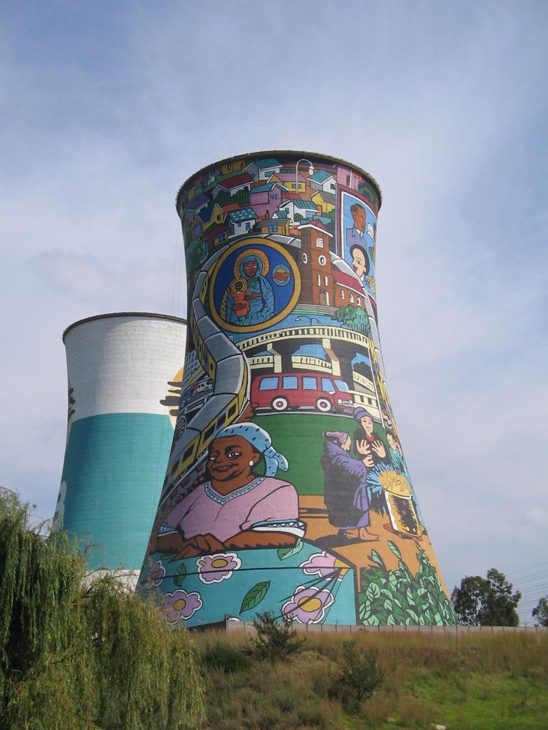
Cooling tower

http://www.jujuwebdesign.com/photos/SouthAfrica/Soweto/images/cooling_tower.jpg

Cooling towers
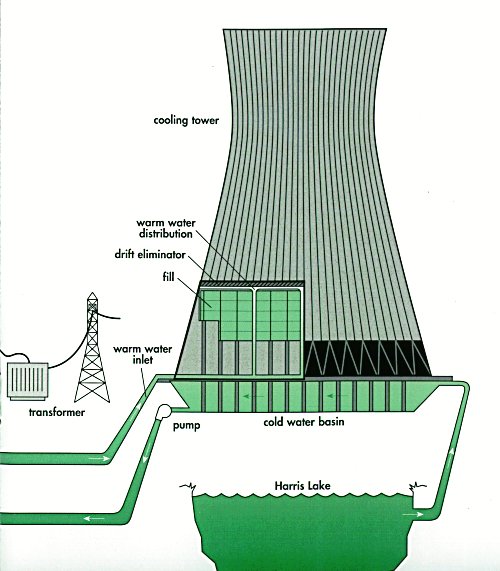
are heat removal devices used to transfer process waste heat to the atmosphere. Cooling towers may either use the evaporation of water to remove process heat and cool the working fluid to near the wet-bulb air temperature or rely solely on air to cool the working fluid to near the dry-bulb air temperature. Common applications include cooling the circulating water used in oil refineries, chemical plants, power stations and building cooling. The towers vary in size from small roof-top units to very large hyperboloid structures that can be up to 200 metres tall and 100 metres in diameter, or rectangular structures that can be over 40 metres tall and 80 metres long. Smaller towers are normally factory-built, while larger ones are constructed on site.

A hyperboloid cooling tower was patented by Frederik van Iterson and Gerard Kuypers in 1918.

http://www.nucleartourist.com/images/ct-natur.jpg


Functions

Cooling Towers have one function:

  • Remove heat from the water discharged from the condenser so that the water can be discharged to the river or recirculated and reused.

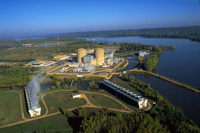
Some power plants, usually located on lakes or rivers, use cooling towers as a method of cooling the circulating water (the third non-radioactive cycle) that has been heated in the condenser. During colder months and fish non-spawning periods, the discharge from the condenser may be directed to the river. Recirculation of the water back to the inlet to the condenser occurs during certain fish sensitive times of the year (e.g. spring, summer, fall) so that only a limited amount of water from the plant condenser may be discharged to the lake or river. It is important to note that the heat transferred in a condenser may heat the circulating water as much as 40 degrees Fahrenheit (F). In some cases, power plants may have restrictions that prevent discharging water to the river at more than 90 degrees F. In other cases, they may have limits of no more than 5 degrees F difference between intake and discharge (averaged over a 24 hour period). When Cooling Towers are used, plant efficiency usually drops. One reason is that the Cooling Tower pumps (and fans, if used) consume a lot of power.

Major Components

Cooling Tower(Supply) Basin

Water is supplied from the discharge of the Circulating Water System to a Distribution Basin, from which the Cooling Tower Pumps take a suction.

Cooling Tower Pumps

These large pumps supply water at over 100,000 gallons per minute to one or more Cooling Towers. Each pump is usually over 15 feet deep. The motor assembly may be 8 to 10 feet high. The total electrical demand of all the Cooling Tower pumps may be as much as 5% of the electrical output of the station.

Gas Compressor

A gas compressor is a mechanical device that increases the pressure of a gas by reducing its volume.

http://www.compressorworld.com.au/uploads/images/Centrifugal-Compressors.jpg

Compressors are similar to pumps: both increase the pressure on a fluid and both can transport the fluid through a pipe. As gases are compressible, the compressor also reduces the volume of a gas. Liquids are relatively incompressible, so the main action of a pump is to pressurize and transport liquids.

http://www.manturbo.com/cmsupload/process/pub/img_centrifugal_b.jpg

Centrifugal compressors

Centrifugal compressors use a muskan rotating disk or impeller in a shaped housing to force the gas to the rim of the impeller, increasing the velocity of the gas. A diffuser (divergent duct) section converts the velocity energy to pressure energy. They are primarily used for continuous, stationary service in industries such as oil refineries, chemical and petrochemical plants and natural gas processing plants.
Their application can be from 100 horsepower (75 kW) to thousands of horsepower. With multiple staging, they can achieve extremely high output pressures greater than 10,000 psi (69 MPa).

Many large snow-making operations (like ski resorts) use this type of compressor. They are also used in internal combustion engines as superchargers and turbochargers. Centrifugal compressors are used in small gas turbine engines or as the final compression stage of medium sized gas turbines.

Diagonal or mixed-flow compressors are similar to centrifugal compressors, but have a radial and axial velocity component at the exit from the rotor. The diffuser is often used to turn diagonal flow to the axial direction. The diagonal compressor has a lower diameter diffuser than the equivalent centrifugal compressor.

Axial-flow compressors are dynamic rotating compressors that use arrays of fan-like aerofoils to progressively compress the working fluid. They are used where there is a requirement for a high flow rate or a compact design.

The arrays of aerofoils are set in rows, usually as pairs: one rotating and one stationary. The rotating aerofoils, also known as blades or rotors, accelerate the fluid. The stationary aerofoils, also known as a stators or vanes, decelerate and redirect the flow direction of the fluid, preparing it for the rotor blades of the next stage. Axial compressors are almost always multi-staged, with the cross-sectional area of the gas passage diminishing along the compressor to maintain an optimum axial Mach number. Beyond about 5 stages or a 4:1 design pressure ratio, variable geometry is normally used to improve operation.

Axial compressors can have high efficiencies; around 90% polytropic at their design conditions. However, they are relatively expensive, requiring a large number of components, tight tolerances and high quality materials. Axial-flow compressors can be found in medium to large gas turbine engines, in natural gas pumping stations, and within certain chemical plants.


Centrifugation

Centrifugation is a process that involves the use of the centrifugal force for the separation of mixtures, used in industry and in laboratory settings. More-dense components of the mixture migrate away from the axis of the centrifuge, while less-dense components of the mixture migrate towards the axis. Chemists and biologists may increase the effective gravitational force on a test tube so as to more rapidly and completely cause the precipitate ("pellet") to gather on the bottom of the tube. The remaining solution is properly called the "supernate" or "supernatant liquid". The supernatant liquid is then either quickly decanted from the tube without disturbing the precipitate, or withdrawn with a Pasteur pipette.

http://www.roanokeai.com/centrifuge.jpg

The rate of centrifugation is specified by the acceleration applied to the sample, typically measured in revolutions per minute (RPM) or g. The particles' settling velocity in centrifugation is a function of their size and shape, centrifugal acceleration, the volume fraction of solids present, the density difference between the particle and the liquid, and the viscosity.

In the chemical and food industries, special centrifuges can process a continuous stream of particle-laden liquid.

It is worth noting that centrifugation is the most common method used for uranium enrichment, relying on the slight mass difference between atoms of U238 and U235 in uranium hexafluoride gas.

Centrifugation in Biotechnology

Microcentrifuges and Superspeed Centrifuges

In microcentrifugation, centrifuges are run in batch to isolate small volumes of biological molecules or cells (prokaryotic and eukaryotic). Nuclei is also often purified via microcentrifugation. Microcentrifuge tubes generally hold 1.5-2 mL of liquid, and are spun at maximum angular speeds of 12000-13000 rpms. Microcentrifuges are small and have rotors that can quickly change speeds. Superspeed centrifuges work similarly to microcentrifuges, but are conducted via larger scale processes. Superspeed centrifuges are also used for purifying cells and nuclei, but in larger quantities. These centrifuges are used to purify 25-30 mL of solution within a tube. Additionally, larger centrifuges also reach higher angular velocities (around 30000 rpm), and also use a larger rotor.

Ultracentrifugation

Ultracentrifugation makes use of high centrifugal force for studying properties of biological particles. While microcentrifugation and superspeed centrifugation are used strictly to purify cells and nuclei, ultracentrifugation can isolate much smaller particles, including ribosomes, proteins, and viruses. Ultracentrifuges can also be used in the study of membrane fractionation. This occurs because ultracentrifuges can reach maximum angular velocites in excess of 70000 rpm. Additionally, while microcentrifuges and supercentrifuges separate particles in batch, ultracentrifuges can separate molecules in batch and continuous flow systems.

In addition to purification, analytical ultracentrifugation (AUC) can be used for determination of macromolecular properties, including the amino acid composition of a protein, the protein's current conformation, or properties of that conformation. In analytical ultracentrifuges, concentration of solute is measured using optical calibrations. For low concentrations, the Beer-Lambert law can be used to measure the concentration. Analytical ultracentrifuges can be used to simulate physiological conditions (correct pH and temperature).

In analytical ultracentrifuges, molecular properties can be modeled through sedimentation velocity analysis or sedimentation equilibrium analysis. In sedimentation velocity analysis, concentrations and solute properties are modeled continuously over time. Sedimentation velocity analysis can be used to determine the macromolecule's shape, mass, composition, and conformational properties. During sedimentation equilibrium analysis, centrifugation has stopped and particle movement is based on diffusion. This allows for modeling of the mass of the particle as well as the chemical equilibrium properties of interacting solutes.

Centrifugation Analysis

Lamm Equation

Particle dispersion and sedimentation can be analyzed using the Lamm equation. The calculation of the sedimentation coefficient and diffusion coefficient is useful for determining the physical properties of the molecule, including shape and conformational changes. However, the Lamm Equation is most ideal for modeling concentrations of ideal, non-interacting solutes. Chemical reactions are unaccounted for by this equation. Additionally, for large molecular weight particles, sedimentation is not always smooth. This may lead to the overestimation of the diffusion coefficient, or oscillation effects at the bottom of a solution cell.

http://kaizen-llc.com/cars_in_yard.jpg

Sigma Analysis

Sigma Analysis is a useful tool determining centrifuge properties. It is similar to the continuity equation that relates volumetric flow rate Q, fluid velocity u, and flow path cross-sectional Area A:

Q = uA

In the case of sigma analysis, u is replaced by vg,the settling velocity at centripetal acceleration of g (9.81 m/s2), Σ replaces area, and is a property of the type of centrifuge, and Q is the input fluid flow rate. Σ has the same units as area.

Q = vgΣ